Medical battery design directly affects the safety and performance of medical devices. Every design engineer asks an important question at the start of a project: what steps make a successful battery pack? This guide gives practical, step-by-step advice for technical professionals. Each section gives a close look at design decisions, from specification to compliance. No background history appears; the content stays on design choices that affect patient safety. Protection circuits, enclosure design, and smart monitoring get practical treatment. Readers learn clear steps for selecting chemistry and adding safety features. Engineers use these principles to create reliable medical device batteries. The guide covers regulatory testing without extra theory. The content helps them meet compliance and safety.
Key Takeaways
-
Start by defining voltage and capacity to match the device’s power needs.
-
Pick the NMC vs. LFP battery chemistry comparison based on how much energy it holds, how safe it is, and how many charge cycles it lasts.
-
Use a battery management system to guard against overcharge, overdischarge, and short circuits.
-
Design the enclosure to survive sterilization and allow cell swelling.
-
Follow IEC 62133-2:2017+A1:2021 and IEC 60601-1:2005+A1:2012+A2:2020 standards to make sure you are safe and follow the rules.

Core Specifications for Medical Battery Design
Voltage, Capacity, and Configuration
Every medical battery design considerations begins with clear electrical goals. Engineers set the nominal voltage and capacity ratings before picking any physical parts. The device’s power profile decides these numbers. An infusion pump needs steady low current for hours. A defibrillator needs a short burst of high current. These different needs lead to different cell setups.
Cells connect in series to raise voltage. They connect in parallel to raise capacity. A pack with four cells in series and two in parallel gives a certain voltage and capacity. Designers figure out the total energy the pack must deliver. They also check the peak current the device pulls. These two values set the smallest cell count. The setup then shapes the pack’s size and weight. This step directly affects medical battery pack design.
Chemistry Selection and Cycle Life
Chemistry choice is a key part of medical battery design. Each chemistry brings trade-offs in energy density, cycle life, safety, and cost. The table below compares three common options.
| Chemistry | Energy Density (Wh/kg) | Medical Application Suitability |
|---|---|---|
| Lithium-ion | 150–200 | Portable medical equipment where compact size and high energy are essential |
| LiFePO4 | 90–120 | Stationary medical equipment and backup power supplies needing high safety |
| NiMH | Moderate (lower than Li-ion) | Medical pumps with moderate energy needs and less emphasis on size |
Lithium-ion packs give the highest energy density. This edge makes them dominant in portable medical devices and handheld instruments. LiFePO4 offers lower energy density but better safety and longer life. NiMH gives moderate energy density with a shorter cycle life, often 300–500 cycles.
Cell swelling is a failure mode to think about during specification. Overcharge or high temperature can cause it. Designers must leave room for slight expansion. Operating conditions also matter. High ambient heat speeds aging in all rechargeable medical equipment batteries. Cold lowers available capacity. These factors guide battery chemistry and construction choices. They also shape battery design choices for the final pack.
Charge, Discharge, and Protection for Custom Medical Battery Packs
Charging Profiles and Algorithms
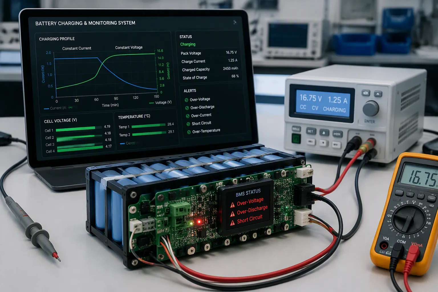
Charging a medical battery pack needs a profile that fits the cell chemistry. custom lithium-ion battery solutions usually use a constant-current, constant-voltage method. The charger sends a steady current until the pack hits its voltage limit. Then it holds that voltage while the current slowly drops. This two-step approach stops overcharge and makes cycle life longer.
The charging algorithm must also think about temperature. Charging below freezing or above a safe limit harms cells. A well-built charger pauses or lowers current outside the safe range. For a custom medical battery, the algorithm often includes cell balancing. Balancing keeps all cells at similar voltages during charge. This step shields weaker cells from repeated stress.
Protection Circuits and Fault Handling
A battery management system (BMS) gives the lithium battery safety engineering for medical device batteries. The BMS constantly checks temperature, voltage, current, state of health, and state of charge. It compares this data against set safety limits. When conditions go outside those limits, the BMS acts.
A fault condition happens when current rises sharply while voltage drops fast. This can cause a short circuit, ground fault, device failure, reverse polarity, overloading, or fire. The BMS handles these events through specific responses:
| Fault Condition | How the BMS Handles It |
|---|---|
| Over-voltage (overcharge) | Checks every individual cell voltage. When any single cell goes past its upper limit, the BMS triggers a contactor disconnect. |
| Over-discharge (under-voltage) | Opens the contactor when a cell falls below its lower limit, stopping anode collapse and permanent capacity loss. |
| Short circuit | Finds the huge current spike within milliseconds and opens the contactor in microseconds. |
| Sustained overcurrent | Enforces continuous overcurrent protection to stop operation at damaging C-rates. |
Redundant BMS protection adds a second layer of safety. If the primary circuit fails, a backup path still disconnects the pack. Physical safeguards work with the BMS. Insulating cell terminals creates a non-conductive barrier against accidental contact. Grid enclosures separate cells and cushion against mechanical shock, vibration, or drops. These critical safety requirements ensure fail-safe operation under fault conditions.
Mechanical Design for Medical Battery Packs
Form Factor and Mounting
The shape of the device decides the battery form factor. A wearable monitor needs a Li-Po pack under 5mm thick. A defibrillator uses 18650 cylindrical cells for high power. NiMH cells cost less but weigh more. Lead-acid batteries stay too heavy for portable gear. A custom medical battery often fills an odd space inside the device. The mounting system holds the pack steady against shock and vibration. Good mounting also helps manage heat dissipation. Connector strain relief stops power interruptions. These choices shape the medical battery pack. A strong medical battery pack design considers all these factors.
Sealing and Sterilization
Medical facilities sterilize devices between patients. Common methods include autoclaving, EtO gas, and gamma radiation. The enclosure material must survive repeated cycles without breaking down. Sealing stops fluid from getting in. Gaskets and ultrasonic welding create the barrier. The designer picks materials that work with the sterilization method. Some plastics crack under repeated gamma exposure. The sealing method must last the entire device lifespan. A broken seal lets contamination in. Contamination leads to corrosion and eventual pack failure.
Material selection connects directly to patient safety. One critical safety requirement is making room for cell swelling. Batteries expand a little over their life. The enclosure must allow this expansion without stressing internal connections. This prevents shorts and keeps the pack reliable. Testing the prototype seal is a required step for any custom medical battery. The mechanical design must include operational details from the start. This ensures a long and safe service life for the medical battery.
Smart Features for Medical Battery Packs
Fuel Gauging and State-of-Health Monitoring
A fuel gauge tells you how much battery power is left. It measures the current going in and out of the pack. It uses coulomb counting to track the net charge. The algorithm also checks voltage and temperature to fix any drift. This mix keeps state-of-charge readings reliable across the full discharge range.
State-of-health monitoring tracks how the pack wears down over time. The gauge records capacity loss with each cycle. It also watches for internal resistance growth. These values tell the device when the pack no longer meets performance requirements. A medical device can then warn the user before the battery causes a critical failure. Without accurate fuel gauging, a patient monitor might shut down at a dangerous moment. The gauge gives the system enough warning to finish a procedure or switch to backup power.
Communication Protocols and Alerts
The fuel gauge needs a way to talk to the host device. Two common interfaces are SMBus and I2C. SMBus works as a variant of I2C designed for smart battery systems. It uses a two-wire serial bus for data transfer. The host reads voltage, current, temperature, and state-of-charge through this bus. I2C offers a simpler protocol with similar capabilities. A custom smart medical battery communication often uses SMBus for its built-in alert features.
Alerts and fault notifications reach the device or user through multiple paths. The SMBus Alert communication lets the gauge send an interrupt signal when a parameter goes outside safe limits. The host device then reads the fault status and takes action. The device can show a warning on its display. It can also sound an audible alarm. Some systems send the alert to a central nurse station. For safety, the medical battery pack can also cut power through a hardware signal independent of the communication bus. This dual path ensures fault notification reaches the system even if the serial bus fails. The medical battery must deliver reliable notifications under all operating conditions.
Safety and Regulatory Compliance in Medical Battery Design

Key Standards and Testing
Safety and regulatory compliance are the foundation of every medical battery project. Engineers must know which battery safety standards apply before they lock in any design choice. IEC 62133 covers battery pack safety for portable sealed cells and batteries. It sets test limits for overcharge, overdischarge, short circuit, and thermal abuse. A pack that fails these tests cannot be sold.
IEC 60601-1 governs electrical safety and electromagnetic compatibility for medical devices. This standard applies to the whole device, including its medical device batteries. The table below shows what IEC 60601-1 requires for battery-operated devices during EMC testing.
| Configuration Aspect | EMC Requirement for Battery-Operated Devices |
|---|---|
| Power Modes | Devices must be tested in both battery and mains power modes |
| Smart Batteries | User-removable smart batteries with embedded electronics require separate ESD immunity testing |
| System Completeness | All accessories, components, and subsystems must be connected during testing |
| Non-Medical Equipment | Included if it affects immunity pass/fail criteria |
| Patient Simulation | Patient simulators used where required by the standard |
| Wireless Technology | Active connections at each antenna during testing |
IEC 60364-7-710:2021 addresses electrical installations in healthcare facilities. Designers reference it when a medical battery system connects to building wiring or charging infrastructure. Together, these three standards define the testing path for any medical battery design.
Risk Management and Documentation
Risk management is a critical safety requirement under ISO 14971:2019. The process starts with finding every possible failure mode. Cell swelling, thermal runaway, short circuits, and connector faults all go on the list. Engineers then rate each risk by how serious and how likely it is. They add controls to reduce high risks to an acceptable level. The BMS protection circuits described earlier serve as one such control.
Documentation proves that safety compliance work happened. A typical file includes the risk analysis, test reports for each battery safety standard, cell datasheets, and the BMS specification. It also holds sterilization validation records and material safety data. Regulators review this file during audits. Missing documents can delay or block safety certifications.
Testing must cover both normal and fault conditions. Engineers run overcharge, overdischarge, short circuit, crush, drop, and thermal cycling tests. Each test result goes into the compliance file. A medical battery that passes all tests earns its lithium battery certifications and regulations. The design team then releases the pack for production. This process repeats for every design change that affects safety. Strong documentation keeps the medical battery traceable through its entire service life.
Making batteries for medical devices follows a clear path. Engineers begin by setting the voltage and capacity they need. They add protection circuits and a BMS to keep the device safe. The mechanical design looks at form factor, sealing, and sterilization. Smart features track state-of-charge and send out alerts. Following IEC 62133 and IEC 60601-1 proves the battery is safe. Safety and regulatory compliance are not things you add later. These rules shape every choice, from the chemistry to the enclosure materials. Readers should use these ideas right away on their next project. Check the relevant standards first. Talk to a battery design expert for help with complex applications. A well-designed medical battery protects patients and meets strict regulatory standards.
FAQ
How does a designer choose the right battery chemistry for a medical device?
The device’s power needs drive this choice. Lithium-ion packs give high energy for portable gear. LiFePO4 gives better safety for stationary equipment. NiMH works for pumps with medium energy needs. Designers compare energy, cycle life, safety, and cost to the device’s needs.
What protection features does a medical battery management system provide?
BMS cell voltage and protection functions, temperature, current, and charge level. It cuts power during overcharge, overdischarge, or short circuit. A backup path also disconnects the pack for extra safety. Physical guards like insulation and enclosures work with the electronics.
Which sterilization methods work with medical battery enclosures?
Autoclaving, EtO gas, and gamma radiation are common ways. The enclosure material must survive many cycles without breaking. Some plastics crack under repeated gamma rays. Gaskets and ultrasonic welding keep fluids out. Designers pick materials that work with the chosen method.
How do smart batteries communicate alerts to medical devices?
SMBus and I2C are two common ways. The SMBus Alert protocol sends a signal when a value goes past safe limits. The host device reads the fault and responds. A hardware signal can also cut power on its own if the bus fails.
What standards govern medical battery safety and testing?
IEC 62133 covers battery pack safety for sealed cells. IEC 60601-1 covers electrical safety and EMC for the whole device. IEC 60364 covers electrical setups in healthcare places. ISO 14971 defines the risk management process. Documents prove compliance during audits.