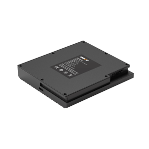
The principle of lithium battery protection board is very simple, electronic components are also very few, it is suitable for beginners to introduce the first chapter of the composition and main role of lithium battery protection board mainly introduces the composition of the battery protection board, the main role of the battery protection board, working principle. And the production of single lithium battery protection line application scope, electrical performance parameters, main materials, size specifications, and other items of the relevant content. All project standards described in this specification can be used as quality inspection standards and basis. (1) liquid lithium ion rechargeable battery; (2) polymer lithium ion rechargeable battery. One, the composition of the protective plate lithium battery (rechargeable) need protection, is determined by its own characteristics. Because the material of the lithium battery itself determines that it cannot be overcharged, over discharge, over current, short circuit and ultra-high temperature charge and discharge, so the lithium battery lithium battery components always follow a delicate protective plate and a piece of current protector. Lithium battery protection function is usually performed by protection circuit boards and PT synergy, protective plate is composed of electronic circuits, and 40 ℃ to + 85 ℃ under the environment of time accurate monitoring batteries voltage and circuit current and the real-time control on and off in current loop; PTC prevents severe battery damage at high temperatures.
The protection plate usually includes control IC, MOS switch, resistor, capacitor and auxiliary device NTC, ID memory, etc. The control IC controls the MOS switch on under normal circumstances to make the cell communicate with the external circuit, and when the cell voltage or circuit current exceeds the specified value, it immediately (tens of milliseconds) controls the MOS switch off to protect the safety of the cell. The NTC is the abbreviation of Negative temperature coefficient, meaning that the negative temperature coefficient, when the environment temperature, the resistance is reduced, use electrical equipment or charging equipment timely response and control internal interrupt and stop charging and discharging. ID storage is typically single-line interface storage, and ID is short for Identification, which stores information such as the type of battery and the date of manufacture. It can act as the limitation of product traceability and application
Second, the general requirements in the main function of protection plate – 25 ℃ ~ 85 ℃ when the Control (IC) testing batteries voltage Control and charge and discharge circuit of the working current, voltage, under the condition of normal C – MOS switch tube conduction, the normal work of the batteries and the protection circuit board, and when the batteries voltage or working current in the circuit exceeds comparison circuit preset Control IC, the within 15 ~ 30 ms (different Control IC and C – MOS have different response time), the CMOS shut off, shut down or charge batteries discharge circuit, to ensure the safety of users and batteries. The working principle diagram of the protection board: as shown in the figure, the IC is powered by the cell, and the voltage can be guaranteed to work reliably at 2v-5v. 1, overcharge protection, overcharge protection resume when the battery was charging voltage more than the set value of VC (4.25-4.35 V, voltage depends on the specific overcharge protection IC) after VD1 flip to Cout is a low level, T1 cut-off, stop charging. When the battery voltage fall to VCR (3.8-4.1 V, recovery voltage depends on the specific overcharge protection IC), Cout is a high level, T1 conduction charging continue, VCR VC must be smaller than a fixed value, in order to prevent frequent jump. 2, put the protection and over discharge protection resume when the battery voltage drops to set data due to discharge of VD (2.3-2.5 V, voltage depends on the specific overcharge protection IC), VD2, with short time delay, make it become a low level, Dout T2 cutoff, discharge to stop, when the battery is in charge of internal or reverse the door was again and make the T2 conduction to prepare for the next discharge. 3, overcurrent, short circuit protection when the circuit charge and discharge circuit current exceeds the set value or is short circuit, short circuit detection circuit action, so that the MOS tube off, current cut-off. The third chapter introduces the function of main parts of protection board
R1: reference supply resistance; The voltage division circuit is formed with the internal resistance of IC to control the level flip of the internal over-charge and over-discharge voltage comparator; General in the resistance of 330 Ω, 470 Ω more; When packaging format (expressing it in standard element length and the width of the element size, such as 0402) identifies the device length and width were 1.0 mm and 0.5 mm) is larger, can use digital identifies its resistance, such as SMD resistor on digital id 473, indicates that the resistance of 47000 Ω 47 k Ω immediately (the third digit in the top two digits 0) after it. R2: overcurrent, short circuit detection resistance; By detecting the VM terminal voltage control current protection plate, welding, damage will cause the battery over current, short circuit protection, general Ω Ω resistance to 1 k, 2 k. R3: ID identification resistor or NTC resistor (described earlier) or both. Conclusion: the resistance in the protective plate is black patches, use multimeter can measure its value, its value when encapsulate larger numerically, said method as mentioned above, of course is proposed.theoretical usually have deviation, each resistance has accuracy specifications, such as 10 K Ω resistance specifications for + / – 5% accuracy, its value is 9.5 K Ω – 10.5 K Ω range for qualified. C1 and C2: since the voltage at both ends of the capacitor cannot be suddenly changed, it plays the role of transient voltage stabilization and filtering. Summary: the capacitor is yellow patch in the protection plate. There are many packaging forms of 0402 and a few of 0603 (1.6mm long and 0.8mm wide). Multimeter is used to inspect its resistance to infinity or general M Ω level; Capacitor leakage will produce large power consumption, short circuit without self – recovery phenomenon. FUSE: ordinary FUSE or PTC (Positive Temperature Coefficient, means positive temperature coefficient); Prevent unsafe large current and high temperature discharge, PTC has self – recovery function. Summary: FUSE is generally A white patch in the protection plate. Provided by LITTE company, it will mark the character d-t on the FUSE, which means the rated current that FUSE can withstand. For example, the rated current of D is 0.25A, S is 4A and T is 5A. Now all FUSE with rated current of 5A in our company, namely, identify character 'T' on the ontology. U1: control IC; All functions of the protection board are realized by IC controlling c-mos to perform switching actions by monitoring the voltage difference between vdd-vss and vm-vss. Cout: overcharge control terminal; The MOS switch is controlled by the MOS T2 gate voltage. Dout: over discharge, over current, short circuit control terminal; The MOS switch is controlled by the MOS T1 gate voltage. VM: overcurrent, short circuit protection voltage detection terminal; Overcurrent and short circuit protection (U (VM) =I*R (MOSFET)) is realized by detecting voltage at VM end. Summary: IC is generally the packaging form of 6 pins in the protection plate. The method to distinguish the pins is as follows: the first pin is near the black point marked on the package body, and then the second, third, fourth, fifth and sixth pins are rotated counterclockwise. If there is no black dot mark on the encapsulation body, the first pin is at the bottom left of the character on the encapsulation body, and the rest pins go counterclockwise) c-mos: field effect switch tube; The implementor of the protection function; Continuous welding, spurious welding, spurious welding, breakdown will cause battery no protection, no display, low output voltage and other adverse phenomena. Summary: CMOS is generally a packaging form of 8 pins in the protection plate. It is composed of two MOS tubes, which are equivalent to two switches, respectively controlling overcharge protection, overdischarge protection, overcurrent protection and short circuit protection. Its pin distinguishing method is the same as IC. Under normal circumstances, Vdd is high level, Vss and VM are low level, and Dout and Cout are high level. When any parameter of Vdd, Vss and VM is transformed, the level of Dout or Cout will change, and at this time, MOSFET will perform the corresponding action (open and close circuit), so as to realize the protection and recovery function of the circuit. Chapter 4 main performance test method 1. NTC resistance test: directly measure the NTC resistance value with a multimeter, and then compare it with the reference guide of temperature change and NTC resistance value. 2. Identification resistance test: directly measure the identification resistance value with a multimeter, and then compare it with the protection plate important project management table. 3. Self-consumption test: the constant current source is 3.7v /500mA; The multimeter is set as uA file, and the meter pen is inserted into the uA connector hole, and then connected in series with the constant current source to connect the protection plate B+ and B-, as shown in the figure below: at this time, the reading of the multimeter is the power consumption of the protection plate, if there is no reading, use tweezers or tin wire to short connect B- and P-, and activate the circuit. 4. Short circuit protection test: connect the battery cell to the protection plate B+ and B-, and short connect B- and P- with tweezers or tin wire, and then short connect P+ and P-; After the short circuit, use a multimeter to measure the open circuit voltage of the protection plate (as shown in the figure below); Repeatedly short 3-5 times, this time the reading of the multimeter should be consistent with the cell, the protection plate should be no smoke, burst and other phenomena.
As shown in the figure above, connect the circuit, set the lithium yi 'an data according to the important project management table, then press the automatic button, and then press the button on the red pen for testing. At this time, the light of the lithium yi 'an tester should be lit one by one, indicating that the performance is OK. Press the display key to check the test data: 'Chg' means overcharge protection voltage; Overdischarge protection voltage of 'Dis' meter; 'Ocur' means overcurrent protection current. 1, no display, output voltage low, can not carry the load: this kind of bad first rule out the bad cell (the cell was no voltage or voltage low), if the bad cell should test the power consumption of the protection plate, to see if the protection plate power consumption is too large to cause the cell voltage low. If the cell voltage is normal, it is because the whole circuit of the protection plate is blocked (components virtual welding, false welding, FUSE bad, PCB board internal circuit is blocked, through hole is blocked, MOS, IC damage, etc.). The specific analysis steps are as follows :(1) use the multimeter black watch pen to connect the negative electrode of the battery core, and the red watch pen is connected to both ends of FUSE and R1 resistance successively. The Vdd, Dout, Cout ends and P+ ends of IC (assuming the cell voltage is 3.8v) are analyzed step by step. These test points should all be 3.8v. If not, there is a problem with this section of the circuit. 1. Voltage changes at both ends of FUSE: test whether FUSE is on, if it is, the internal circuit of PCB board is blocked; If not, FUSE has problems (poor incoming material, over-current damage (MOS or IC control failure), and materials have problems (FUSE is burnt out before MOS or IC action), and then FUSE is connected with a short wire for further analysis. 2. Voltage changes at both ends of R1 resistance: test the resistance value of R1. If the resistance value is abnormal, it may be virtual welding and the resistance itself is broken. If the resistance value is not abnormal, there may be a problem with the internal resistance of IC. 3. Voltage change at IC test terminal: Vdd terminal is connected with R1 resistor. If the Dout and Cout ends are abnormal, it is because of IC virtual welding or damage. 4. If there is no change in the front voltage, test the abnormal voltage between B- and P+, then it is because the positive pole of the protection plate is blocked. (2) the red multimeter pen is connected to the positive electrode of the cell. After activating the MOS tube, the black watch pen is connected to the p-terminal of MOS tube 2, 3, 6 and 7 feet. 1. If the voltage of MOS tube 2, 3, 6 and 7 feet changes, the MOS tube is abnormal. 2. If the MOS tube voltage does not change and the p-terminal voltage is abnormal, it is because the negative pole of the protection plate is blocked. 2. Short circuit without protection: 1. If there is a problem with VM terminal resistance, a multimeter and a pen can be used to connect IC2 pin. See if there is any virtual welding between resistor, IC and MOS pin. 2.IC and MOS abnormality: because over-discharge protection shares a MOS tube with over-current and short-circuit protection, if the short-circuit abnormality is caused by MOS problem, this board shall have no over-discharge protection function. 3. The above are defects under normal conditions, and short-circuit abnormalities caused by poor configuration of IC and MOS may also occur. For example, the earlier bk-901, whose model is' 312D ', has a long delay time in the IC, resulting in the damage of MOS or other components before the IC makes the corresponding action control. Note: the easiest and most direct way to determine whether the IC or MOS is abnormal is to replace the suspect components. Short circuit protection without self-recovery: 1. The IC used in the design originally has no self-recovery function, such as G2J, G2Z, etc. 2. The short-circuit recovery time of the instrument is too short, or the load is not removed during the short-circuit test, for example, the meter pen is not removed from the test end after short-circuit test with the multi-meter voltage range (the multi-meter is equivalent to a load of several megabytes). 3. Leakage between P+ and P-, such as rosin with impurities between the solder pads, yellow glue with impurities or capacitance between P+ and P- is broken down, and ICVdd to Vss is broken down (resistance value is only a few K to several hundred K). 1. As MOS internal resistance is relatively stable and large, the first thing to be suspected is FUSE or PTC, which are relatively easy to change. 2. If FUSE or PTC resistance is normal, the inspection of P+, P- through resistance between the welding plate and the component surface by the structure of the protective plate may lead to micro-breakage and relatively large resistance. 3. If there are no problems above, it is necessary to doubt whether MOS is abnormal. Second, the thickness of the kanban (whether it is easy to bend), because bending may lead to abnormal pin welding; Then the MOS tube is put under the microscope to observe whether it breaks. Finally, multimeter is used to test the MOS pin resistance value to see whether it is broken down. 1. The ID resistance itself is abnormal due to virtual welding, fracture or poor resistance material: the two ends of the resistance can be rewelded. If the ID is normal after rewelding, it is virtual welding of resistance; if the ID is broken, the resistance will crack in the middle after rewelding. 2.ID through hole no conduction: can test both ends of the hole with a multimeter. 3. Internal circuit problems: scratch the solder block paint to see whether the internal circuit is disconnected or short circuit.
The page contains the contents of the machine translation.